

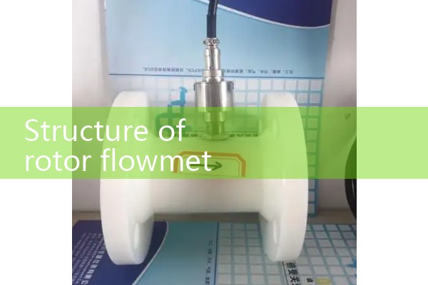
『Structure of rotor flowmeter』Related information(clamp on meter|electromagnetic meter|venturi meterrotameter|orifice meter|ultrasonic flow meter|mass flow meter|coriolis mass flow meter|coriolis flow meter|magnetic flow meter|magmeter flow meter|magflow flow meter|mag meter flow meter|electromagnetic flow meter|vortex flow meter|turbine flow meter|thermal mass flow meter|thermal flow meter|rotameter flow meter)
1. Working principle of gas rotor flowmeter
The working principle of gas rotor flowmeter is that when gas flows through a vertical conical tube from bottom to top, it will push a freely suspended rotor (or float) inside the tube to rise. After reaching an equilibrium position, the rotor comes to a standstill, and the lift of the gas on the rotor is exactly equal to its gravity. By reading the corresponding position of the rotor on the scale of the conical tube, the instantaneous flow rate value of the gas can be directly obtained. 1. The core workflow is based on the principle of variable area measurement: - Gas enters from the bottom of the flowmeter, passes through the annular gap between the rotor and the inner wall of the conical tube, and flows out from the top. -When the gas flow rate increases, the lift generated by the gas on the rotor increases, which will cause the rotor to find a new equilibrium point in a wider conical tube area, that is, the rotor rises and the annular area increases, resulting in a larger angle. -When the rotor is stable, its gravity (minus gas buoyancy) reaches dynamic equilibrium with the pressure differential force (lift) generated by the gas on the vibration source rotor. -The suspension height of the rotor is approximately linearly related to the volumetric flow rate of the gas, and the flow rate value can be directly read through the celery scale on the cone tube.
2. Key components • Cone tube: usually made of glass, metal, or plastic, with a scale on the inner wall, and the diameter gradually decreases from top to bottom. • Rotor (float): an induction element suspended in a conical tube, with various shapes such as spherical and inclined groove, and a material densit
2. How should I read a rotor flowmeter? Why?
The reading method for the rotor flowmeter is as follows: For the sub flowmeter reading method, stand in front of the flowmeter, with your eyes parallel to the float, and move your line of sight horizontally to the left until you see the outline of the float touching the positioning line. The corresponding reading value is at the intersection of the positioning line and the horizontal scale in the middle of the float.. A rotor flowmeter measures fluid flow based on the principle of throttling, but it changes the flow area of the fluid to maintain a constant differential pressure between the upper and lower parts of the rotor. Therefore, it is also known as a variable flow area constant
 Hot Product
 Related AD