

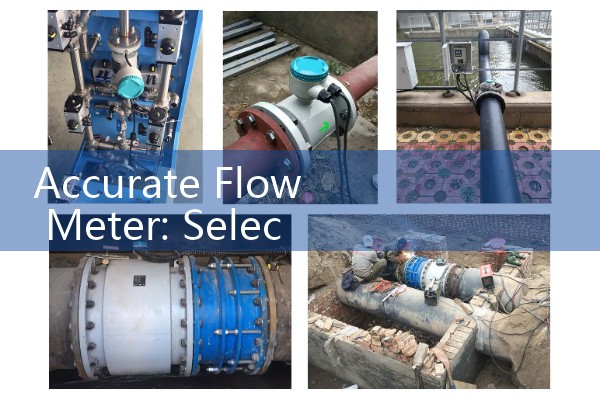
『Accurate Flow Meter: Selecting Premium High-Precision Processing Sensors』Related information(clamp on meter|electromagnetic meter|venturi meterrotameter|orifice meter|ultrasonic flow meter|mass flow meter|coriolis mass flow meter|coriolis flow meter|magnetic flow meter|magmeter flow meter|magflow flow meter|mag meter flow meter|electromagnetic flow meter|vortex flow meter|turbine flow meter|thermal mass flow meter|thermal flow meter|rotameter flow meter)
Accurate Flow Meter: Selecting Premium High-Precision Processing Sensors
Quick Answer: The accuracy of any industrial flow meter starts with the machining quality and signal processing stability of its primary sensor. For custody transfer, batch dosing, or water cut measurement, we recommend electromagnetic and Coriolis meters with PT100 temperature compensation and 4-20 mA HART output as the baseline. If your fluid has viscosity above 50 cP or you need ATEX Zone 1 certification, the sensor choice shifts immediately to oval gear or dual-tube Coriolis designs with all-welded construction.
We tell every engineer who calls us the same thing. You do not buy a flow meter for its enclosure. You buy it for the sensor block and the way the electronics condition the raw signal. In our calibration lab outside Nanjing we have tested meters from a dozen sensor suppliers. The difference between a DN25 flow sensor that drifts 0.3 percent after three months and one that holds 0.1 percent for two years is rarely the measurement principle. It is the processing precision of the electrodes, the coil winding tension in electromagnetic meters, the alignment of the vibrating tubes in Coriolis meters, and the thermistor placement in thermal mass meters.
Why the Sensor Processing Chain Defines Real Accuracy in the Field
When a specification sheet lists accuracy as 0.2 percent of reading, that number assumes the sensor was machined to a repeatable roughness, welded without introducing mechanical stress, and aged properly before the first calibration run. Most engineers skip this part. They compare datasheets between brands and assume all DN50 electromagnetic meters perform the same way. We have seen this on customer sites many times. A wastewater plant in Malaysia replaced six low-cost spool-piece magmeters with Silver Instruments models using abrasive-resistant PTFE liners and Hastelloy C electrodes. The raw signal from the old sensors had a noise floor of 12 microvolts. The new sensor, processed with a mirror-finish electrode surface and uniform coil winding, dropped the noise floor to 3 microvolts. The plant eliminated a daily 3 percent totalizer discrepancy they had lived with for two years.
Here is the thing about high-precision processing sensors. It is not about adding more digital filters after the ADC. It is about giving the analog front end a cleaner signal to work with. When a Coriolis meter tube is cold-worked unevenly during bending, the two measurement tubes do not vibrate at exactly the same harmonic. The drive circuit compensates by injecting more energy into one side. Over six months that asymmetry grows. The zero point drifts by 20 kg/h on a meter that was factory-zeroed at 0.5 kg/h. We saw this in a paint manufacturing plant in Vietnam last year. A competitor Coriolis meter with a CNC-bent but poorly stress-relieved tube set started under-reading resin flow by 1.7 percent at temperatures above 65 degrees Celsius. The problem disappeared when we replaced it with a Silver Instruments dual U-tube sensor that we annealed for six hours and then matched the two tubes to within 0.05 Hz of each other at the second bending mode.
Temperature and Pressure: The Two Variables That Expose Sensor Build Quality
Any flow sensor is a mechanical structure. When you inject 180 degree Celsius thermal oil into a DN15 Coriolis meter, the measuring tubes expand by about 0.12 millimetres. If the tube geometry is not symmetric or the manifold casting has residual internal stress, that expansion twists the tubes off axis. The meter interprets the twist as a mass flow offset. Most buyers do not have the ability to run a temperature loop test on a flow meter before procurement. They trust the factory data. Our process for premium sensor builds includes a thermal soak cycle from minus 40 to 200 degrees Celsius repeated five times before we weld the tube assembly into the housing. The tube frequency is recorded at each plateau. The frequency shift must stay within 0.08 percent across the full span. If a sensor block fails this test, we scrap it.
Pressure is the other hidden variable. A vortex flow meter with a DN100 wafer body that is rated for 40 bar will see its bluff body deflect by a few microns under full line pressure. That micron-level deflection changes the Strouhal number just enough to create a 0.4 percent measurement shift between 5 bar and 40 bar. The fix is not a thicker bluff body. That kills the low-flow signal. The fix is a stiffer body profile machined from a single bar stock forging with the pressure tap integrated, not a separate welded-on boss. Silver Instruments uses this monoblock machining approach for all vortex meters above DN50. A desalination plant in Saudi Arabia running brine at 38 bar confirmed the advantage. They swapped ten vortex meters to our monoblock design. The brine mass balance closure improved from 2.1 percent to 0.6 percent without any change in the automation system.
Sensor Material Processing and Chemical Compatibility at the Micro Level
Here is where things get specific. A magnetic flow meter liner might be listed as PTFE or PFA. What the datas
For oval gear meters measuring solvents like ethyl acetate or MEK, the gear material processing is critical. A gear blank cut from PPS bar stock by standard machining will have surface roughness of 0.8 micron Ra. That is fine for diesel. It is not fine for a solvent with 0.4 cP viscosity that acts as a cleaning agent. The solvent wicks into the micro-grooves left by the cutting tool and creates a bypass stream that increases with time. The meter over-registers at first because the clearance gap acts like an orifice. After six weeks the gear faces erode and the meter under-registers. We learned this from a battery chemical supplier in Indonesia. They needed a meter for NMP solvent. Our solution was a PEEK gear pair lapped to 0.3 micron Ra flatness and matched to a chamber honed to the same finish. The meter held 0.5 percent repeatability for 14 months before needing recalibration.
Signal Conditioning That Protects the Sensor Investment
Even the best processed sensor needs electronics that do not degrade its hard-won accuracy. We design our transmitter boards with a key rule. The input-referred noise of the analog front end must be at least six decibels below the sensor minimum signal at the lowest specified flow. For an electromagnetic meter with a 5 microsiemens per cm fluid, the flow signal can be as low as 80 microvolts peak to peak. That means the amplifier must have a noise density below 2 nV per root Hz at 1 kHz. Achieving that requires a low-noise instrumentation amplifier, a carefully laid out ground plane with no ground loops, and a switch-mode power supply that is synchronised to the coil excitation frequency to avoid beat frequencies. Most generic magmeter transmitters skip the synchronisation step. The result is a wandering zero at low conductivity that looks like a grounding problem but is actually conducted EMI from the power supply.
We apply the same discipline to the PT100 temperature sensor that is integrated into many of our flow meters. A Coriolis meter uses the tube temperature to compensate for Young modulus change in the metal. If the PT100 readout has a 0.3 degree Celsius offset due to self-heating from a high excitation current, the density measurement shifts by 0.15 kg per cubic metre, and the mass flow calculation follows. Our temperature front end uses a 100 microamp excitation current instead of the typical 1 milliamp. That cuts self-heating by a factor of 100. It also mandates a precision 24-bit ADC with low drift to resolve the smaller signal. The extra component cost is about eight US dollars. In a custody transfer skid measuring 80 million US dollars of crude oil per month, that eight-dollar decision is almost invisible and eliminates a 0.02 percent mass flow bias.
Frequently Asked Questions on High-Precision Flow Sensors
How do I know if my application needs a premium processed sensor or a standard one?
Look at the cost of measurement error per day. A 0.5 percent error on a 40 cubic metre per hour diesel loading arm costs roughly 1200 US dollars per month in product loss. That justifies a premium sensor with a verified zero-stability trace. If the fluid is water for irrigation with no dosing, a standard sensor is sufficient.
Can a high-precision sensor survive abrasive fluids without a liner upgrade?
No. Even the best machined electrode profile wears under quartz sand or iron ore slurry. You need a ceramic or polyurethane liner matched to the particle size. We ask customers for particle size distribution and solids loading by weight before recommending a sensor material set.
What is the practical repeatability difference between a machined and a cast sensor body?
In vortex meters, a machined bar-stock body consistently delivers 0.2 percent repeatability across a 20 bar pressure range. A sand-cast body can vary by 0.1 percent between units due to internal porosity and dimensional tolerance, which is sometimes acceptable for steam mass balance but not for natural gas sales.
How do you verify sensor precision before shipment?
Our standard is a 5-point water calibration on an ISO 17025 accredited rig with master meters traceable to NMI Australia and NIM China. For Coriolis meters with a viscosity application we add a 2-point oil calibration at 20 cP and 200 cP. Every sensor serial number gets a PDF report with the raw frequency data, not just the error curve.
Do you supply sensors separately from transmitte『SILVER Official Website SERVICE』
 Hot Product
 Related AD